
Burr and Camber in Slit Strip: What the Tolerances Mean
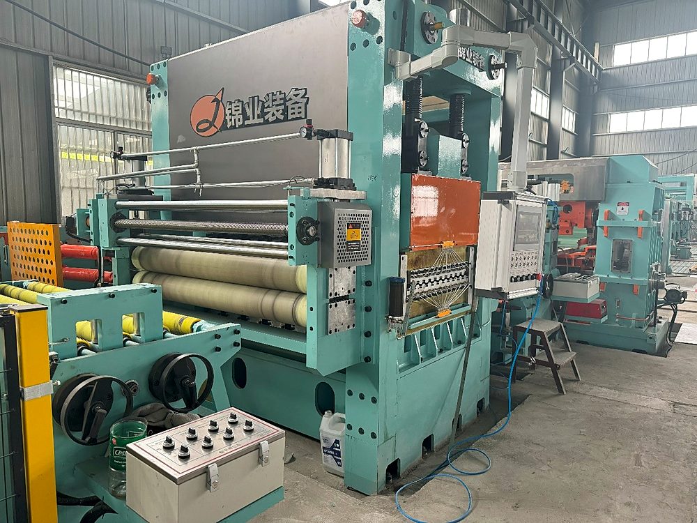
Burr and camber are the two tolerances that decide whether slit strip can go straight into a press or a roll former. Burr is measured as a share of strip thickness — 3% for thin material, 4% for heavier gauge — and camber as a deviation over length, 1.0 mm in 2 m being the normal target. Both are set on the slitter, but only one of them is usually the slitter’s fault.
What burr height actually measures
A sheared edge has four zones: roll-over at the top, a burnished band, a fracture zone, and the burr at the bottom. Burr height is the part that sticks out past the original strip surface. It is measured with a profile gauge or a dial indicator at the strip edge, and it is always quoted against thickness rather than in absolute millimetres — a 0.05 mm burr is negligible on 3 mm strip and unacceptable on 0.5 mm strip.
That is why the specification reads “burr ≤ 3% of thickness” and not “burr ≤ 0.05 mm”. The first travels with the material; the second does not.
Why 3% for thin strip and 4% for heavier gauge
Thin strip is far more sensitive to a burr of the same absolute size. On 0.4 mm sheet, a 0.02 mm burr is already 5% of thickness and enough to catch in a die. On 4 mm plate the same 0.02 mm is invisible and harmless, so the practical limit relaxes.
The second reason is tooling. Thin material is cut with a very small clearance and a sharp blade; heavier gauge needs a larger clearance and accepts a taller burr before the edge becomes a problem downstream. Setting a 3% limit on 12 mm plate would mean changing blades far more often than the edge quality justifies.
Blade clearance is the burr control
Most burr problems are clearance problems, not blade-material problems. Clearance is set as a percentage of thickness — typically in the 5–10% band, with thin strip at the high end of that band and heavy gauge toward the middle — and it has to be reset when the gauge changes.
- Clearance too large — the strip tears instead of shearing. The fracture zone grows, the burr gets tall and ragged, and the edge looks torn under a magnifier.
- Clearance too small — the blade rubs and work-hardens the edge. Burr stays low at first, then rises sharply as the blade wears, and stainless will start to gall.
- Blade worn or chipped — a local burr spike at one strip position, not across the whole coil. This is the signature to look for when only one strip is out of tolerance.
The blade material matters for how long the clearance stays correct, not for whether it is correct. T10, H13, HM-3 and 6CrW2Si sit at different points on wear resistance and toughness; the trade-off between them is covered in the blade material note.
Camber is not always the slitter’s fault
Camber is the bow in the strip as it lies on the floor — measured by putting a straight edge on 2 m of strip and reading the maximum gap. A slit strip can leave a perfectly set slitter and still be out of camber, because camber has four possible sources:
- The incoming coil. A master coil with internal stress will release it when slit. If the mother coil is cambered, every slit strip inherits a share of it.
- Uneven tension across the width. One strip wound tighter than its neighbour pulls the slit band into a curve on the recoiler.
- Leveler set-up. Insufficient or uneven levelling leaves the strip with a memory of the coil set, and the slitter cannot remove it.
- Edge condition. A burr on one side only — from a nicked blade — creates a local stress that shows up as camber over the coil length.
This matters for diagnosis. If camber appears on all strips and follows the mother coil, the answer is in the leveler or in the incoming material. If it appears on one strip only, it is the blade or the spacer at that position.
How camber is measured on the floor
The standard shop-floor method needs no instrument: lay 2 m of strip on a flat surface, place a straight edge along the concave side, and measure the largest gap with a feeler gauge. 1.0 mm in 2 m is the common working target for slit strip; tighter than that usually means the customer is feeding a roll former or a laser-welded blank line where a small bow accumulates over several metres.
Measure it under no tension. Strip measured while still under recoiler tension will read straighter than it really is, and the difference is often the whole tolerance.
What each defect tells you
- Burr on every strip, even height → clearance or blade sharpness, line-wide.
- Burr on one strip only → that blade pair or spacer.
- Burr increasing along the coil → blade wear; check the wear land before resetting clearance.
- Camber on every strip, same direction → incoming coil or leveler.
- Camber alternating side to side → tension difference across the recoiler, or a guide that is fighting the strip.
- Width drifting on one strip → spacer or lock-up, not the blade edge.
When to change blades instead of adjusting
Adjust clearance first, then check tension, then look at the blade. A blade that has been re-ground several times has a wear land that changes the effective clearance even when the setting is unchanged — that is the point at which re-shimming stops working and regrinding or replacement is the cheaper answer.
Practical signs that the blade is finished: burr climbs within a few hundred metres of a fresh set-up, the strip edge shows a bright rubbed band instead of a clean fracture, or stainless starts to pick up material on the blade edge.
How to write the tolerance into a specification
Four lines are enough, and they should be stated per material and per gauge band rather than once for the whole line:
- Burr limit as a percentage of thickness, separate figures for thin and heavy gauge.
- Camber in mm per 2 m, measured under no tension.
- Width tolerance, with the band it applies to — ±0.05 mm below 100 mm wide and 1.5 mm thick, ±0.10 mm otherwise.
- Edge alignment and tower limits in the recoil, typically ±1.0 mm and ±2.0 mm.
Those numbers are what a line is actually commissioned against. A line built to hold 1.0 mm camber in 2 m can be pushed tighter with more levelling and more tension control, but it is a different specification, not a different operator technique. The slitting line range is configured against exactly these figures, and the six-input specification guide shows where they sit among the other inputs.
If you have strip that fails one of these limits now, send the gauge, the material and a photo of the edge. The pattern of the burr usually identifies the cause before anyone visits the line.
More from the workshop
Related news

Industry News
Slitting Stainless Steel: Why It Is Harder Than Mild Steel
Work hardening, cutting force and surface marking: three reasons stainless needs a different slitting line, and what to change in the specification.
Read more
Industry News
What Decides Cut to Length Accuracy on a Coil Line?
Length error comes from the measuring roll, the leveler, shear response and the stacker — where each one costs you millimetres, and what to specify.
Read more
Industry News
Flying, Rotary, Swing or Stop Shear: Choosing a CTL Shear
Stop, swing, rotary or flying: how thickness, speed and surface finish decide which shear a cut to length line is built around.
Read moreTalk to us
Working on a line like this one?
Tell us the coil or sheet you need to produce. We will come back with the configuration, the working range and the delivery schedule that fit your project.
- Material grade, thickness and coil width
- Finished strip width or cut length
- Target output and site conditions